Configure MERGING and Dolby® ATMOS CINEMA PROCESSOR CP850 device in AES67 mode
Notes
As of today, Dolby® CP850 Firmware 2.3.1.4, there are some limitations for this device.
Please consult Dolby website for up to date details
- CP850 cannot be PTP slave.
The Merging devices can be set as PTP slave, but in that case can't be locked to external sync (such as WordClock or video ref) - CP850 doesn't provide device nor source discovery, and doesn't provide SDP retrieving mechanism.
Therefore ANEMAN cannot be used to discover the device, and the streams connections have to be done manually. - The CP850 Atmos/audio configuration is beyond the scope of this document, please consult the Dolby documentation.
System Requirements
- CP850 Firmware V2.3.1.4 (tested)
- Merging Horus / Hapi firmware V3.9.2 (or above) / Anubis firmware V1.0 (or above)
Physical Connections
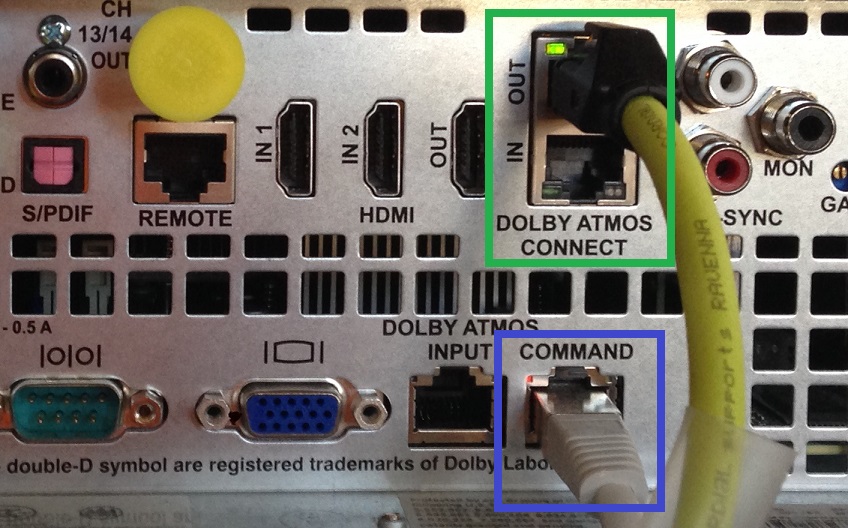
Opposite to Merging devices, the CP850 requires two network connections, one for Control and one for the Audio/AES67 network.
- First connect the COMMAND port to your data network.
This network configuration can be accessed on the unit front display, and can be set to DHCP or static IP depending on your needs.
Please refer to Dolby documentation for further details.
The command network is only required to configure the device, it can be removed once the configuration is finished. - Connect the DOLBY ATMOS CONNECT OUT to your Audio/AES67 network
Note : - To avoid IP addresses issues, make sure the two networks uses different IP addresses range.
Please consult this page for help on configuring IP addresses. - Audio/AES67 network should not be mixed with other networks, and network switches must be properly configured.
Merging keeps a list of validated switches for RAVENNA/AES67 networks, with configuration guides to help you set it up.
Please follow this link to view the list and configuration guides.
CP850 Configuration
- Open the CP850 WebApp in your browser, by typing its Command IP address, and enter your login credentials.
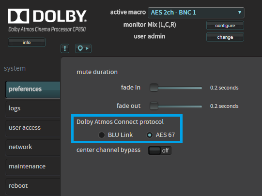
Tip : the command IP address can be found on the device front panel display, in the Network menu. - Go in System > Preferences and set the Dolby Atmos Connect Protocol to AES67.
- Go in System > Network and configure the Dolby Atmos Input.
Set the IP configuration to manual, and enter valid IP address and Netmask. (Gateway can be left to 0.0.0.0)
Disable jumbo frames option should be ticked.
Please click on Apply.
In our example we will use the 169.254.21.120 address and 255.255.0.0 mask.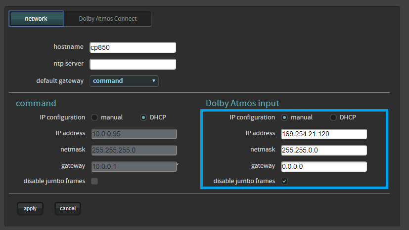
- Now switch to the Dolby Atmos Connect tab.
Make sure legacy mode option is unticked - Set the Static Source IP (= CP850 AES67 IP address)
- PTP Domain Number should be set to 0, and both PTP priorities set to 100.
This will elect the CP850 as PTP GrandMaster. - Destination multicast IP : the destination device multicast IP address.
In our example, the Merging device IP is 169.254.25.20, which according to audio networking convention its Multicast IP is 239.1.25.20 - Source UDP Ports (1-8, 9-16, 17-24,....): 6517, 6519, 6521,...
RTP destination UDP ports (1-8, 9-16, 17-24,....): 6518, 6520, 6522, ....
Please click on Apply.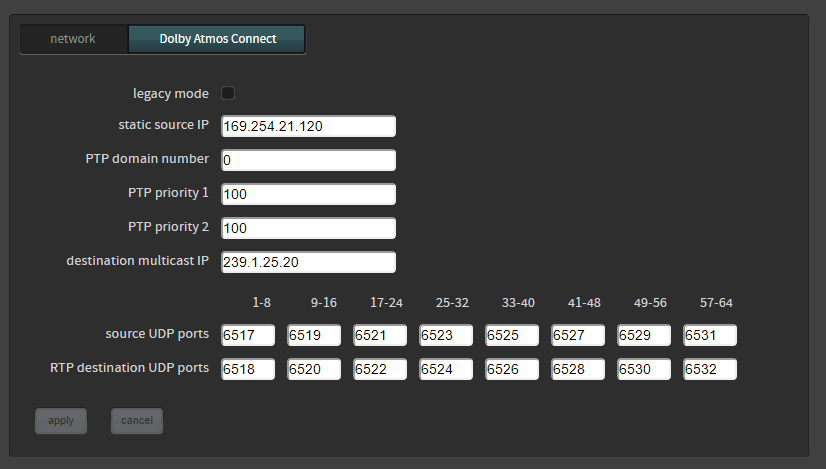
Merging device Configuration
- Set the Merging device sampling rate to 48 kHz.
Make sure the device is set to PTP Slave.
Set the Latency to AES67 (48 smpl).
Please consult the device user manual for further details Open your Merging device advanced page in your browser.
- In the PTP tab, Status section, please note the Master GMID (not the on in the Master section !)
This value will be required later.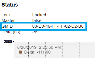
- Go now in the Session Sinks tab.
Press on the Create session sink button
Set your required output in the IO drop down menu.
Set the Channel count to 8 and click on Apply. - Label the connection, in our example we will label it CP850_1
SDP Configuration File
Download our SDP example and open it in a Text editor (notepad or notepad++).
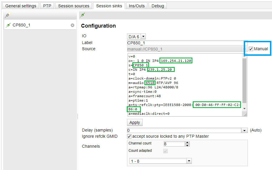
We will now have to adapt it to your network configuration.v=0 no modification o=- 1 0 IN IP4 XXX.XXX.XXX.XXX Enter your Dolby Atmos Connect IP (Point 5 in the CP850 Configuration section above)
In our example :
o=- 1 0 IN IP4 169.254.21.120s=LABELOFYOURSINK Enter your Sink Label, in our example :
s=CP850_1c=IN IP4 239.1.XXX.XXX XXX Enter the Destination Multicast IP you did enter in Dolby Atmos Connect page
(Point 7 in the CP850 Configuration section above), in our example :
c=IN IP4 239.1.25.20t=0
a=clock-domain:PTPv2 0no modification m=audio RTPPORTDESTINATION RTP/AVP 96 RTPPORTDESTINATION is the RTP Destination UDP Port defined in the CP850.
(Point 8 in the CP850 Configuration section above)
In our example :
m=audio 6518 RTP/AVP 96 for channels 1 to 8
m=audio 6520 RTP/AVP 96 for channels 9 to 16a=rtpmap:96 L24/48000/8
a=sync-time:0
a=framecount:48
a=ptime:1no modification a=ts-refclk:ptp=IEEE1588-2008:MASTERGMID MASTERGMID is the PTPMaster ID, that we have noted previously in the
Advanced pages > PTP tab > Status section.
In our example :
a=ts-refclk:ptp=IEEE1588-2008:00-D0-46-FF-FF-02-C2-B6:0a=mediaclk:direct=0
a=recvonlyno modification - Now that the SDP is configured for your network, go back in the Advanced pages > Sync Tab.
- Click on the Manual checkbox, and copy - paste the SDP configuration.
- Click on Apply to confirm the configuration
- If you use an Anubis Monitor Source, you will now have to patch this connection :
-You can go in Anubis Settings > Sources > YourSourceName and select the connection in the Channels section.
-Or you can use patch in the Session Sink. Scroll down and tick the required channels for your Monitor Source ("Player" in our example).
If you use more than 8 channels, please patch the second sink as well.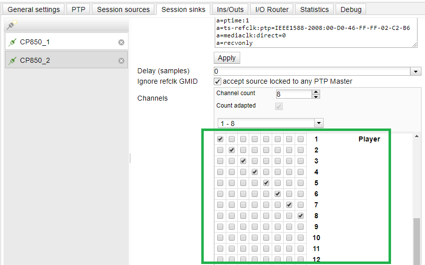
The CP850 is now outputting through the Merging device.
You may now remove the CP850 Command network connection.
Additional remarks
If you need to add more channels (for tracks 9-16, 17-24,....), please modify the RTP Destination UDP Port,
as configured in the CP850 Dolby Atmos Connect Page.
In our example : m=audio 6518 RTP/AVP 96 for channels 1 to 8 / m=audio 6520 RTP/AVP 96 for channels 9 to 16 / ....
PTP Domain :
You may use another PTP domain than 0. In such case you will have to set the domain number in all the devices manually.
You must also modify the SDP description with the correct domain number:
a=clock-domain:PTPv2 DomainNumber => a=clock-domain:PTPv2 109 if you want to use PTP Domain 109
a=ts-refclk:ptp=IEEE1588-2008:MASTERGMID:DomainNumber => in our example a=ts-refclk:ptp=IEEE1588-2008:00-D0-46-FF-FF-02-C2-B6:109