Cisco CBS350 Managed switch manual configuration.
General Info.
This is in no case an exhaustive configuration procedure, It's a simple guide on how to configure these switches to use them with Ravenna/AES67 networks.
Connecting several Cisco switches together requires additional configuration.
Please also see the Multiple network switches considerations page and Cisco SG300/350 Multiple switches configuration guide.
Important note for DANTE-AES67 devices
When Dante devices are connected to a Cisco switch configured with the Merging settings, an additional configuration step is required.
Please follow the instructions below after the switch configuration.
Access CBS350 switch Administration page
- Plug a network cable from the switch and to your computer.
The switch will need to initialize, this will take a few minutes before being accessible. Set your computer to use an IP in the 192.168.1.x address pool.
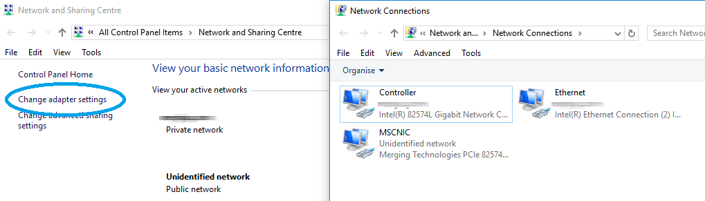
Go in Windows Control Panel > Network and Sharing Center, then click on Change Adapter settings (left)
Right click on the adapter that you have to configure and select Properties.
Select the Internet Protocol Version 4 (TCP/IP), then click on the Properties button.
Set it to "Use the following IP addresses", then enter the IP address. It must be in the same range as the Cisco switch connected on it, for example : adapter IP is 192.168.1.1
The Subnet mask is mandatory; Windows can set it automatically, simply click in the Subnet mask field.
You may need to also change the attached network device(s) IP address, consult their documentation for details.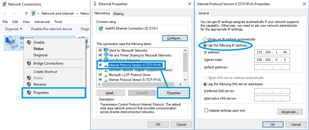
Go in the System Preferences and select Network.
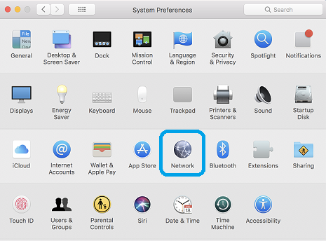
Select the adapter that needs to be configured, and click on the arrow next to Configure IPv4.
Select Manually in the drop down list, and enter the required IP address.
It must be in the same range as the Cisco switch connected on it, for example : adapter IP is 192.168.1.1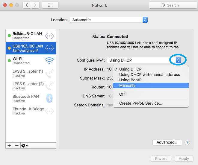
The Subnet mask is mandatory; MacOS can set it automatically, simply click in the Subnet mask field.
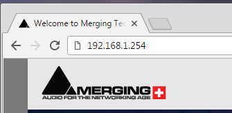
Open a navigator page to navigate to http://192.168.1.254 (Cisco switches default IP address)
Default user name: cisco
Default password: cisco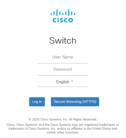
After the login prompt, you will be asked to set your own password.
Please note the minimum character numbers and password complexity required.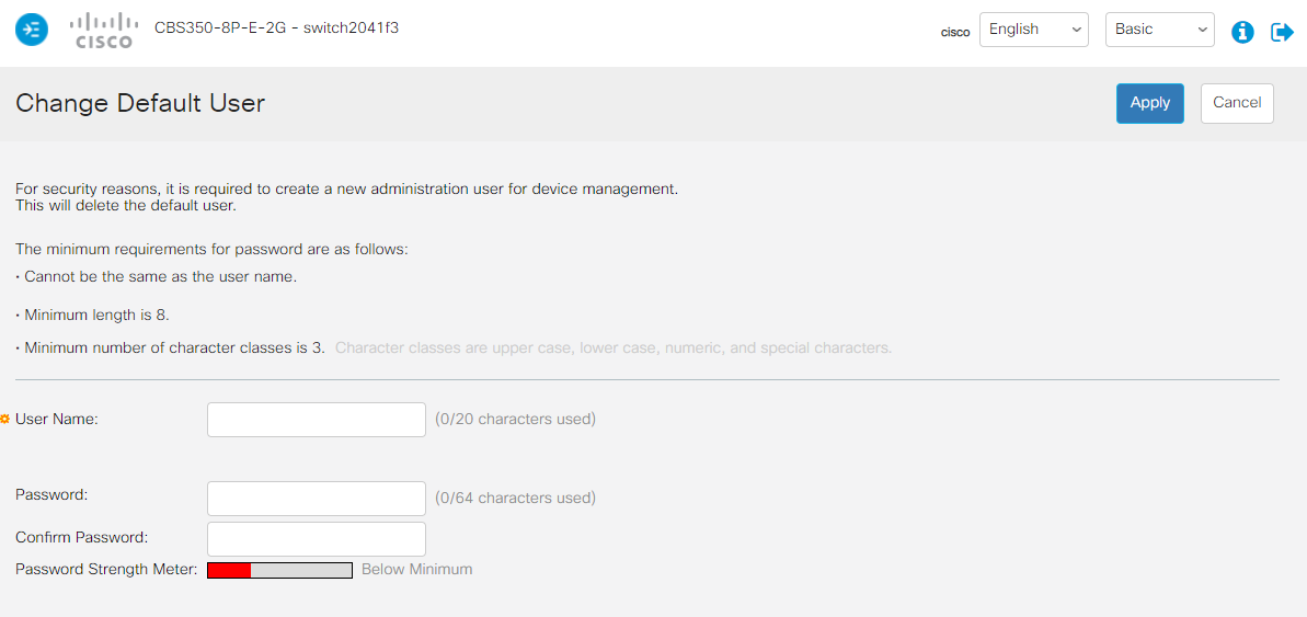
If you wish to change the password later, you will have to go in the Administration > User Accounts page.
Resetting the switch to "factory defaults" will also require to do this step again.- Set the switch in Advanced mode on the top right corner.

For ease of use, please also activate the side bar by clicking on the blue icon on the top left corner.
- By default, the switch will ask you to renew the password every 6 months.
While this behavior enhances the security, you may disable it in Security > Password Strength, by removing the Password Aging option.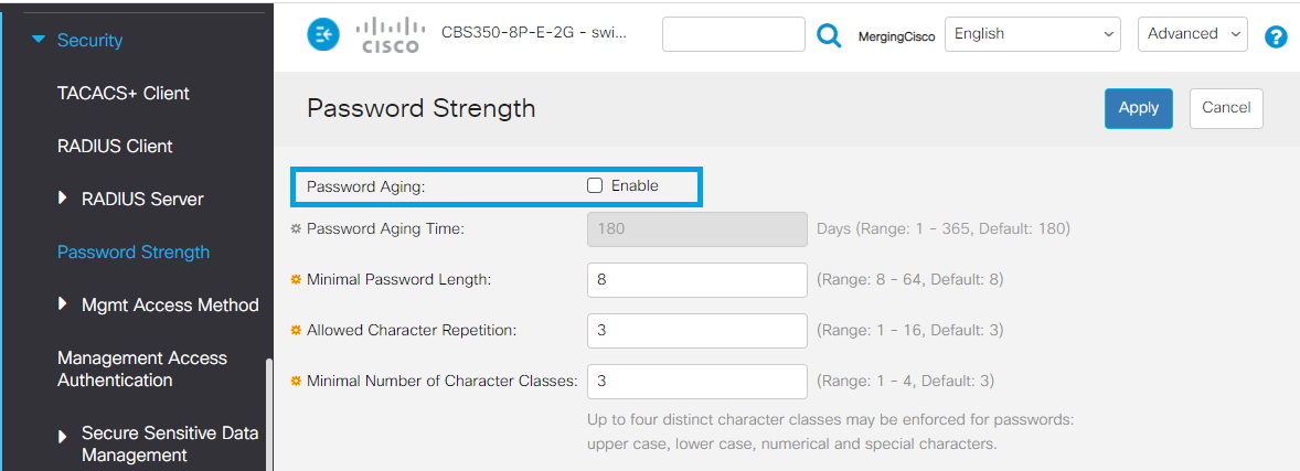
Single VLAN Configuration
The first step is to change the IP configuration to use an APIPA address (Automatic Private Internet Protocol Addressing).
The administration page will then be only accessed trough this new IP.
Setting the switch in the APIPA IP range (169.254.0.0/16) will ensure that you can always access its administration page.
Merging Ravenna devices generally use APIPA IP range to communicate over the network (Network - Auto setting on Horus/Hapi/Anubis/...)
- Browse to IPv4 Configuration > IPv4 Interface
Click on the + button to add a static address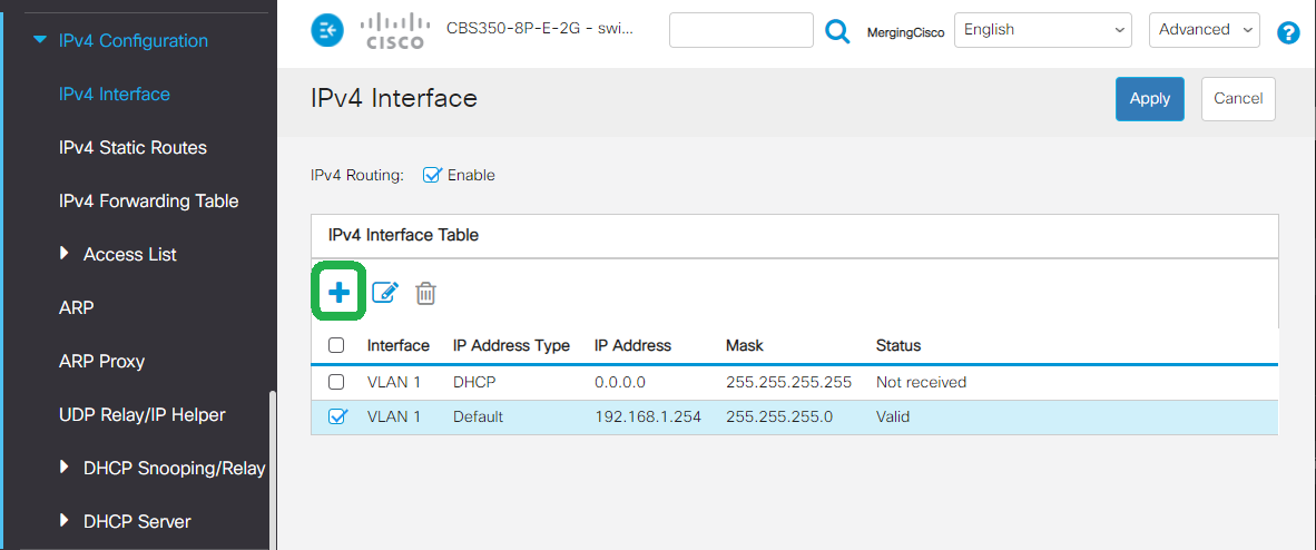
- Set the IP Address type to Static IP Address.
Enter 169.254.1.254 in the IP Address field.
For the Mask setting, select Prefix Length and enter 16.
That will make your switch administration page respond to that IP address.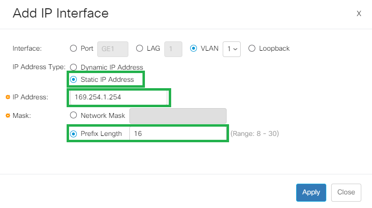
- Click on Apply to save the changes.
The switch will ask you to confirm the change. - The switch will now change its IP address to 169.254.1.254, therefore the 192.168.1.254 page you are actually using will stop responding.
To be able to access the switch now, please set your computer to use an IP in the 169.254.x.x address pool.
Refer to the "How to manually setup an IP address" above, but this time, set your network adapter to automatically obtain an IP address (Windows) - Using DHCP (MacOS)- Enter 169.254.1.254 in your browser, and enter your credentials.
Make sure the switch administration page is in Advanced mode (top right corner) - Please browse to Multicast > Properties.
Set the Bridge Multicast Filtering Status to Enable
Set both Forwarding method for IPv6 and IPv4 to IP Group address.
Click on Apply once done.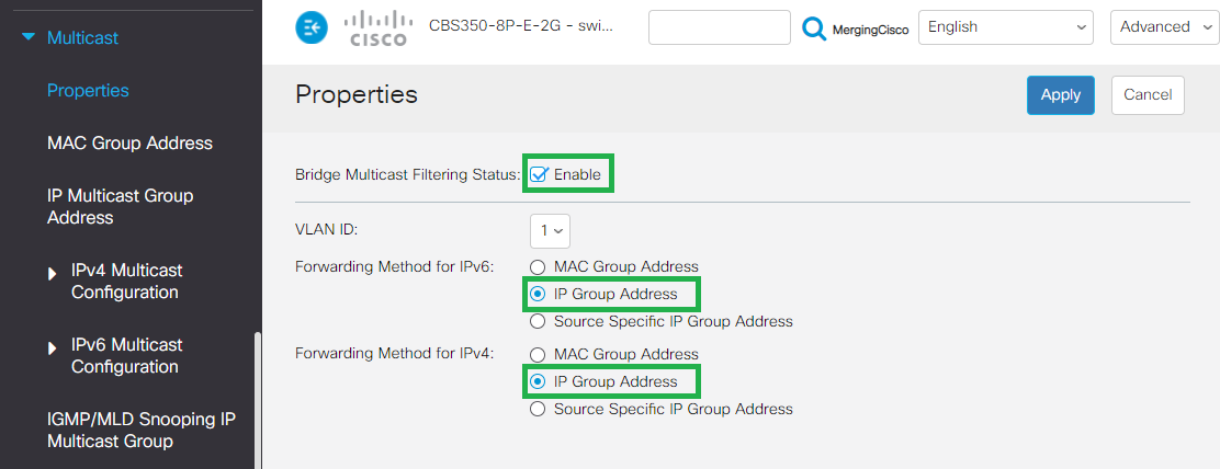
- Now go in Multicast > IPV4 Multicast Configuration > IGMP Snooping.
Enable both the IGMP Snooping Status and IGMP Querier Status checkboxes.
Then click on on Apply.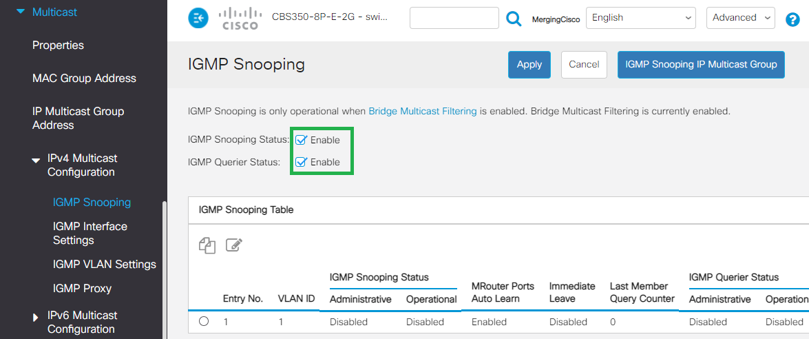
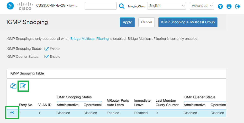
- On the IGMP Snooping Table, click on the radio button to select and then click on the Edit icon.
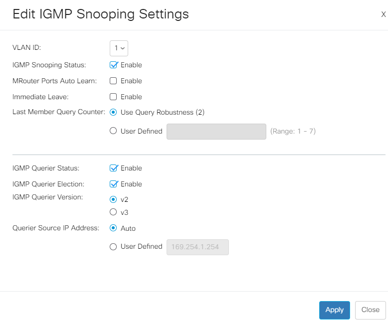
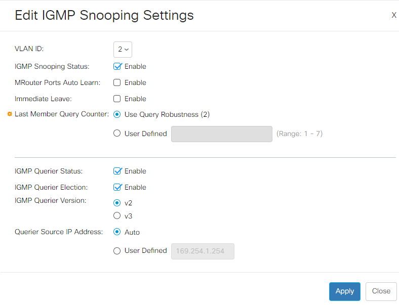
Configure the IGMP Snooping Settings as on the picture below, and click Apply once done.
SSM - IGMP v3
If you plan to use SSM (Source-Specific Multicast - see Merging devices Advanced pages),please activate IGMP v3.
- Go in Multicast > IPV4 Multicast Configuration > IGMP VLAN Settings
Click on the radio button to select and then click on the Edit icon.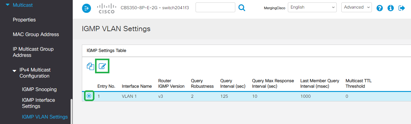
Please set the Router IGMP Version to v2
And the Query Interval to 30
Click on Apply
SSM - IGMP v3
If you plan to use SSM (Source-Specific Multicast - see Merging devices Advanced pages),please activate IGMP v3.
- Browse now to Multicast > Unregistered Multicast
Set all ports to Filtering
Click on Apply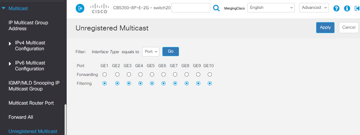
By default, Green Ethernet settings are applied, this needs to be disabled.
Please browse to Port Management > Green Ethernet > Properties
Untick both Energy Detect Mode and Short Reach, and untick 802.3 Energy Efficient Ethernet (IEEE) as well.
Click on Apply once done.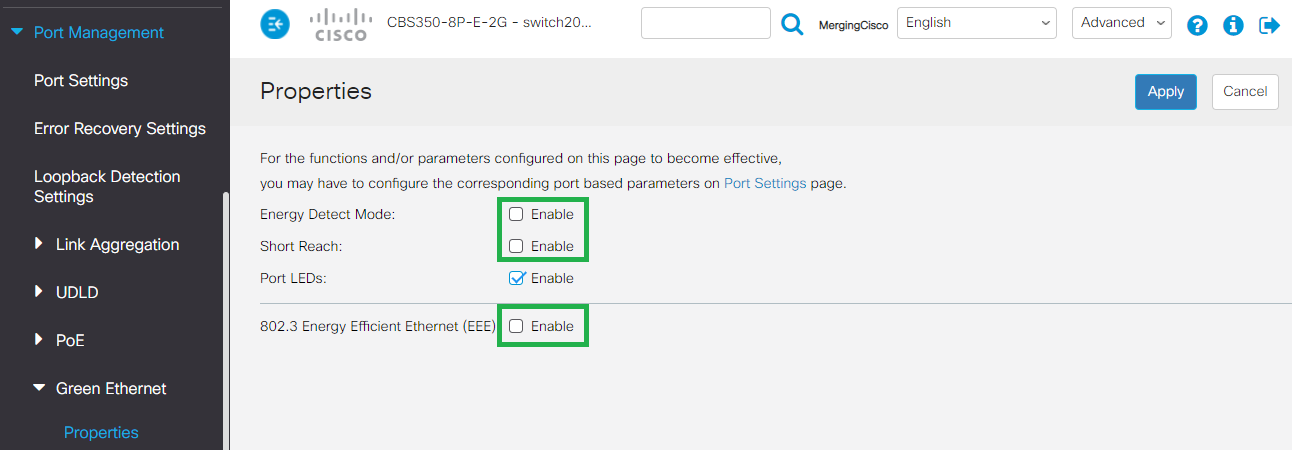
Browse now to Quality of Service > General > QoS Properties.
Set QoS Mode to Basic.
Click on Apply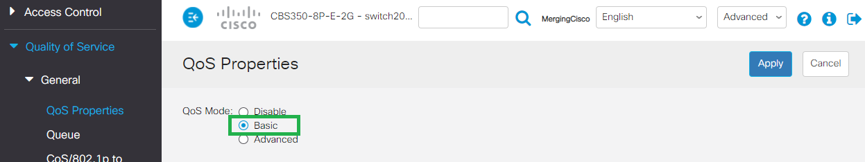
- Go now in Quality of Service > QoS Basic Mode > Global settings.
Set Trust Mode to DSCP
Click on Apply.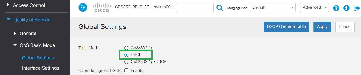
- Go back to Quality of Service > General > DSCP to Queue.
Change the DSCP to Queue Settings as shown in the following picture and click Apply once done.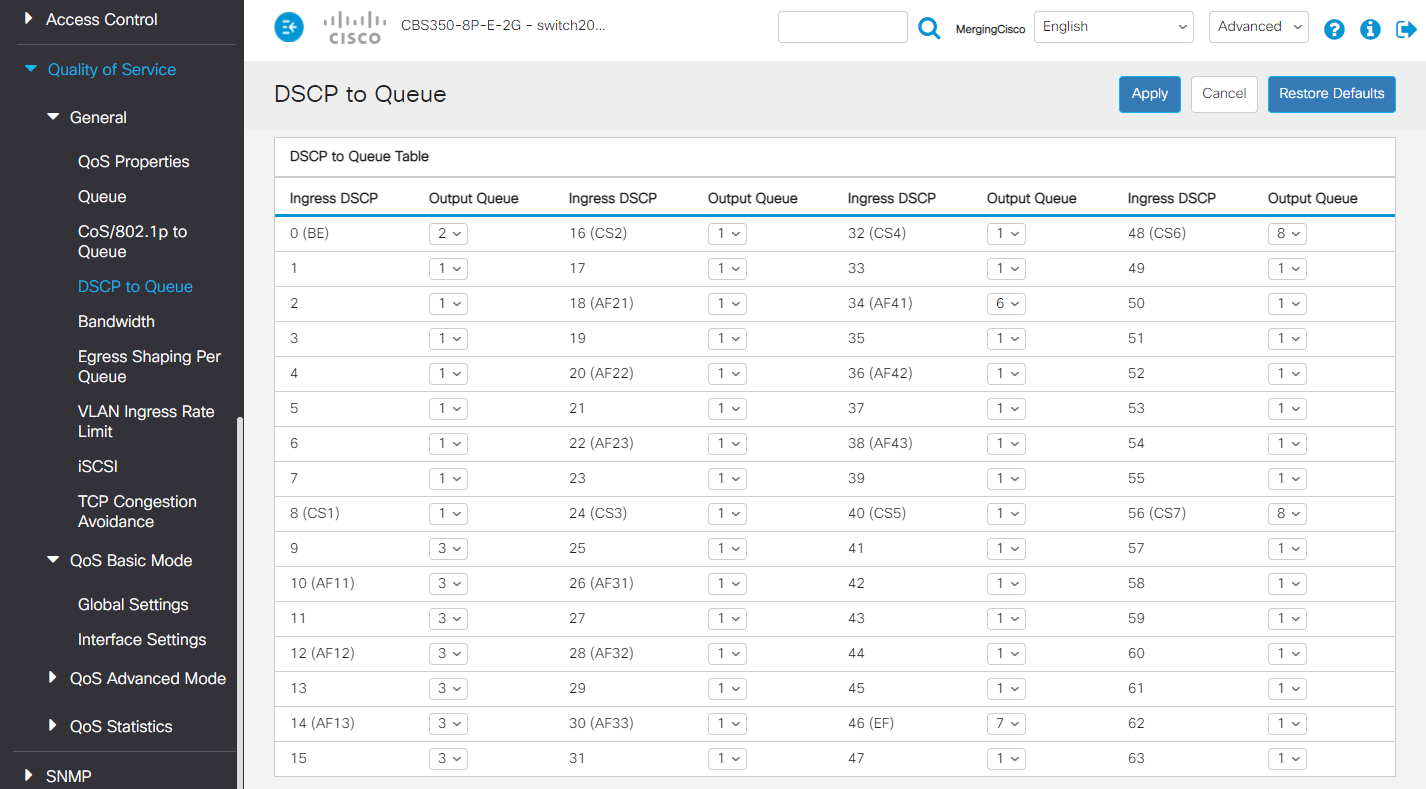
Note : Queue 34 : RTP AES67 / Queue 46 : PTP AES67 / RTP Ravenna / Queue 48 : PTP Ravenna / Queue 56 : PTP Dante Now is a good time to save the configuration.
Go in Administration > File Management > File Operations.
Select Duplicate as Operation Type.
Source File Name : Running Configuration
Destination File Name : Startup Configuration
Click on Apply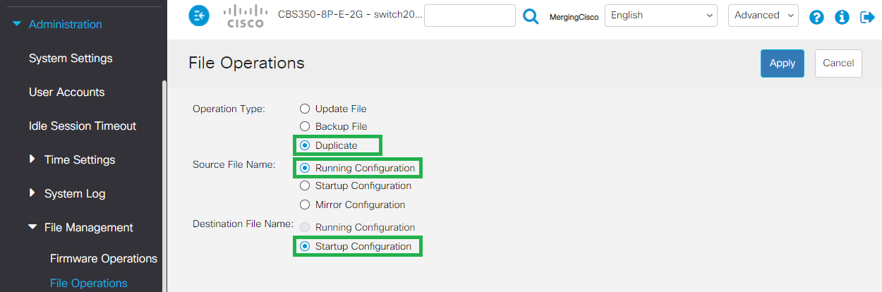
This will apply the current settings to the start up configuration.
In other terms that makes the configuration to be permanent (unless a reset of the device is done).You must now restart the switch for the changes to apply.
Click Administration > Reboot
Select Immediate and click on Reboot button.
Note that the device might take some time to reboot.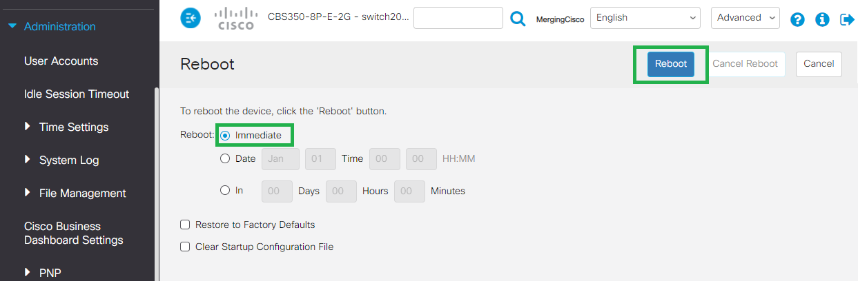
Dual VLAN Configuration
By default the switch already has VLAN1 created with defaults for regular networking.
So we will be adding VLAN2 for the for the Ravenna AES67 networking.
VLAN1 : will be used for regular networking.
VLAN2 : will be used for Ravenna AES67.
Once connected to the switch as described on Access CBS350 switch Administration page.
Note : The switch Administration pages will only be accessible from VLAN 2.
- Go in VLAN Management > VLAN Settings
Click on the + button at the bottom of the VLAN Table.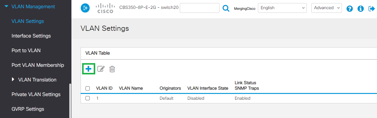
- Set the VLAN ID: 2 and enter a VLAN NAME (can be anything you want, please do not use special characters).
Make sure VLAN Interface Status and Link Status SNMP Traps are both active.
Click on Apply once done.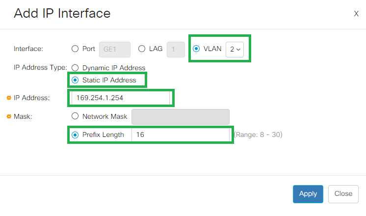
- Go to VLAN Management > Port to VLAN,
In the Filter section, set the VLAN ID to 2, and Interface Type to Port.
Click on Go.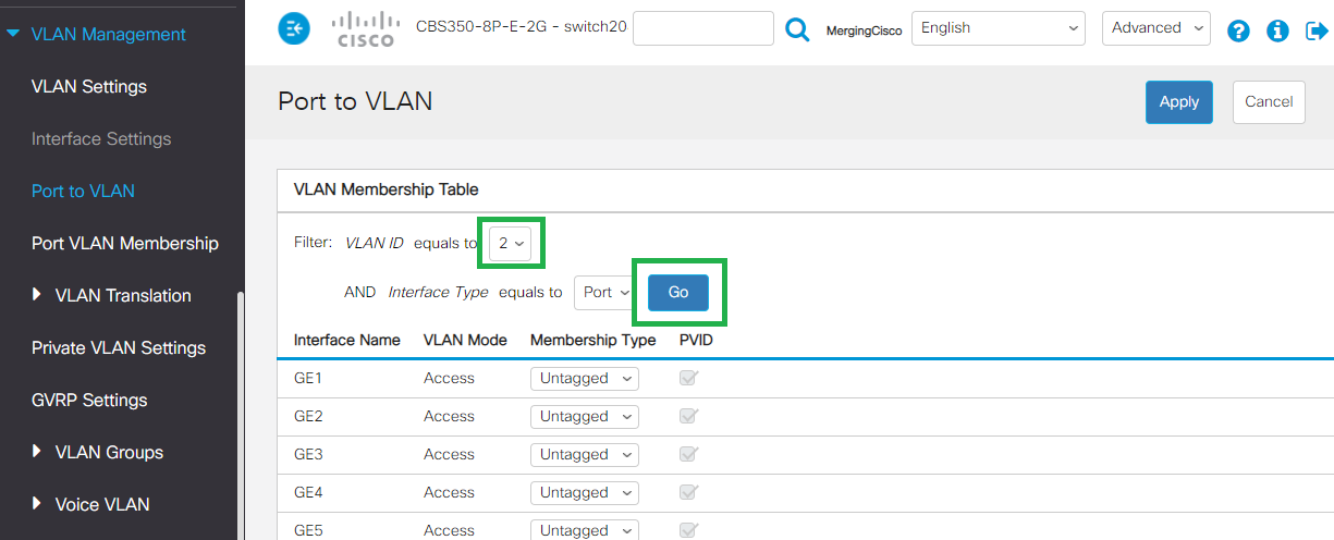
- Now you can see that all ports for VLAN 2 are excluded, you need to assign the required ports to this RAVENNA/AES67 VLAN.
Set the required ports from Excluded to Untagged (in the picture below, ports 5 to 8 and port 10 are assigned to VLAN 2.
Click on Apply once done.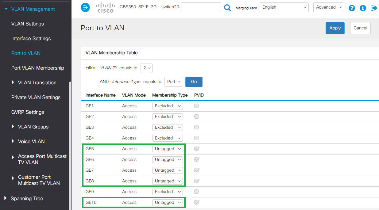
- You may now check your VLAN1 config.
In the Filter section, set the VLAN ID to 1, and Interface Type to Port.
Click on Go.
You can see that the ports you have added to VLAN 2 are excluded from VLAN 1. - Browse to IPv4 Configuration > IPv4 Interface
Click on the + button to add a static address - Make sure VLAN is set to 2
Set the IP Address type to Static IP Address.
Enter 169.254.1.254 in the IP Address field.
For the Mask setting, select Prefix Length and enter 16. - Click on Apply to save the changes.
The switch will ask you to confirm the change. - The switch will now change its IP address to 169.254.1.254, therefore the 192.168.1.254 page you are actually using will stop responding.
To be able to access the switch now, please set your computer to use an IP in the 169.254.x.x address pool.
Refer to the "How to manually setup an IP address" above, but this time, set your network adapter to automatically obtain an IP address (Windows) - Using DHCP (MacOS)- Please make sure you are physically connected to a port assign to VLAN2 (in our example, port 6)
Note : you can do the same operation for VLAN1, to be able to access the Management interface for both VLANs.
But you have to use another IP address (192.168.1.254 for example)
Enter 169.254.1.254 in your browser, and enter your credentials.
Make sure the switch administration page is in Advanced mode (top right corner) - Please browse to Multicast > Properties.
First set the VLAN ID to 2
Set the Bridge Multicast Filtering Status to Enable
Set both Forwarding method for IPv6 and IPv4 to IP Group address.
Click on Apply once done.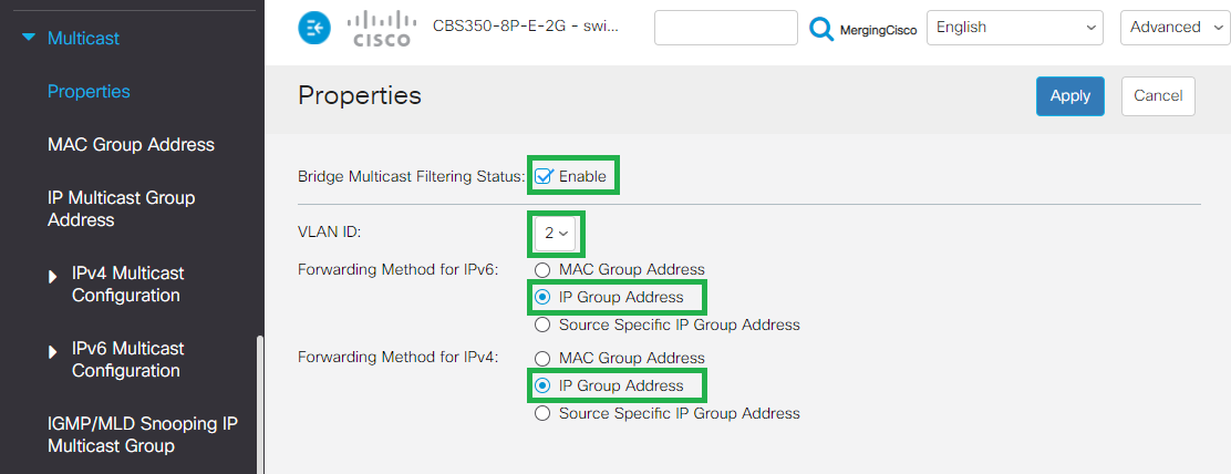
- Now go in Multicast > IPV4 Multicast Configuration > IGMP Snooping.
Enable both the IGMP Snooping Status and IGMP Querier Status checkboxes.
Then click on on Apply. - On the IGMP Snooping Table, click on the radio button on the VLAN ID2 line to select and then click on the Edit icon.
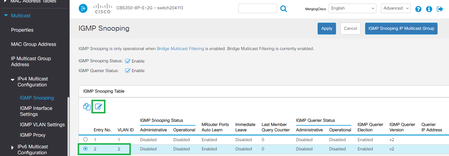
Configure the IGMP Snooping Settings as on the picture below, and click Apply once done.
SSM - IGMP v3
If you plan to use SSM (Source-Specific Multicast - see Merging devices Advanced pages),please activate IGMP v3.
- Go in Multicast > IPV4 Multicast Configuration > IGMP VLAN Settings
Click on the radio button on the VLAN 2 line to select and then click on the Edit icon.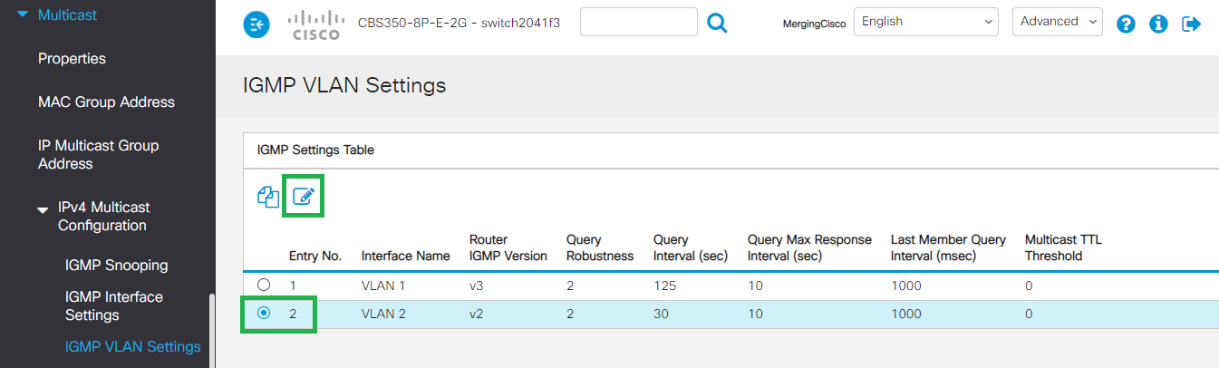
Please set the Router IGMP Version to v2
And the Query Interval to 30
Click on Apply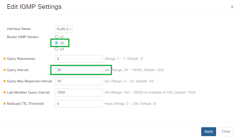
SSM - IGMP v3
If you plan to use SSM (Source-Specific Multicast - see Merging devices Advanced pages),please activate IGMP v3.
- Browse now to Multicast > Unregistered Multicast
Set the ports you have assigned to VLAN 2 to Filtering (in our example, ports 5 to 8 and 10)
Click on Apply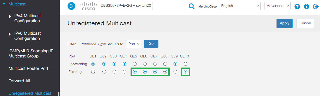
By default, Green Ethernet settings are applied, this needs to be disabled.
Please browse to Port Management > Green Ethernet > Properties
Untick both Energy Detect Mode and Short Reach, and untick 802.3 Energy Efficient Ethernet (IEEE) as well.
Click on Apply once done.Browse now to Quality of Service > General > QoS Properties.
Set QoS Mode to Basic.
Click on Apply- Go now in Quality of Service > QoS Basic Mode > Global settings.
Set Trust Mode to DSCP
Click on Apply. - Go back to Quality of Service > General > DSCP to Queue.
Change the DSCP to Queue Settings as shown in the following picture and click Apply once done.
Note : Queue 34 : RTP AES67 / Queue 46 : PTP AES67 / RTP Ravenna / Queue 48 : PTP Ravenna / Queue 56 : PTP Dante Now is a good time to save the configuration.
Go in Administration > File Management > File Operations.
Select Duplicate as Operation Type.
Source File Name : Running Configuration
Destination File Name : Startup Configuration
Click on Apply
This will apply the current settings to the start up configuration.
In other terms that makes the configuration to be permanent (unless a reset of the device is done).You must now restart the switch for the changes to apply.
Click Administration > Reboot
Select Immediate and click on Reboot button.
Note that the device might take some time to reboot.
Dante AES67 Additional configuration
Please first make sure the Dante device is compatible with AES67.
Consult the Manufacturer or Audinate website.
When Dante devices are connected to a Cisco switch configured with the Merging configuration file, an additional configuration step is required.
Dante AES67 users have to add IP Multicast Groups :
Once the configuration file has been applied, and the switch has been rebooted.
- Connect to the Cisco Administration page (default address with Merging configuration file is 169.254.1.254)
- Make sure the Display Mode of the Cisco Administration page is set to Advanced
- Browse to Multicast > IP Multicast Group Address and click on Add.
- Enter VLAN ID 1 (assuming you have 1 VLAN) and enter 224.0.0.230 as IP Multicast Group Address.
Click on Apply. - Now select the 224.0.0.230 Group and click on Details.
Set the ports connected to Dante devices to Static and click on Apply. - Repeat the same operation for addresses 224.0.0.231, 224.0.0.232 and 224.0.0.233
(Example with Dante devices on port 9-10).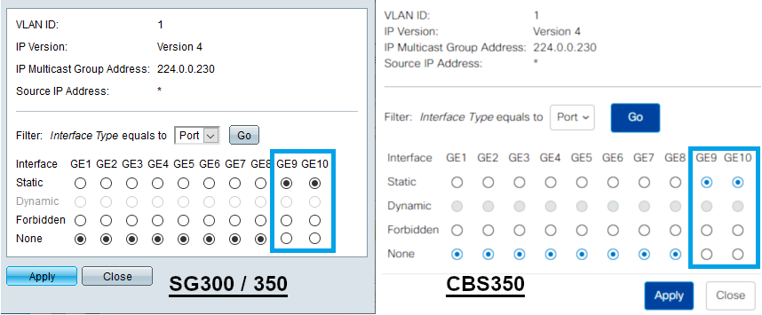
How to Backup and import configuration files
Backup your configuration to a file
This is how to backup your configuration to a file.
- Go to Administration > File Management.
Select File Operations. - Operation Type has to be set to Backup File.
Source File Type : select Running or Startup Configuration, depending on your needs.
Copy Method : HTTP/HTTPS
Sensitive Data Handling : Encrypt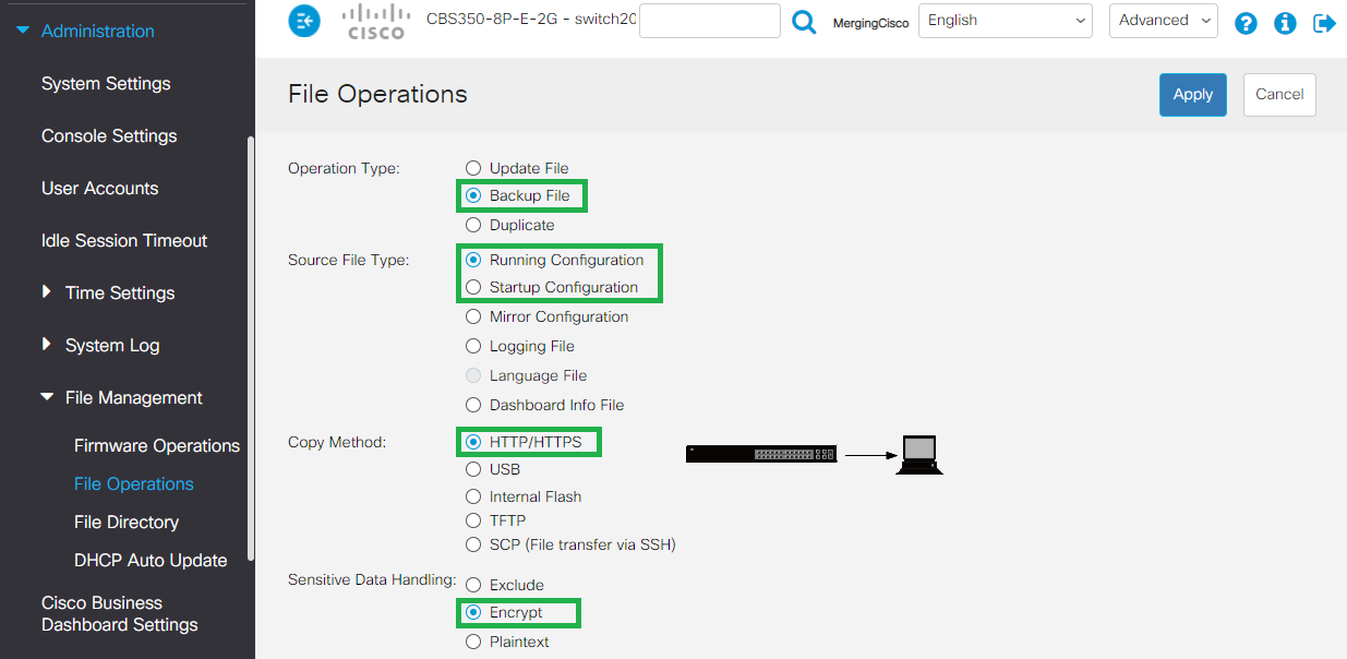
- Click on Apply.
The configuration file can be downloaded in your browser (as a .txt file)
Import a configuration file
IMPORTANT NOTE :
If you try to import a configuration file into the Running Configuration (the current one), it will fail.
What you need to do is import from a configuration file to the startup configuration and then reboot.
- Go to Administration > File Management.
Select File Operations. - Operation Type : Update File
Destination File Type : Startup Configuration
Copy Method : HTTP/HTTPS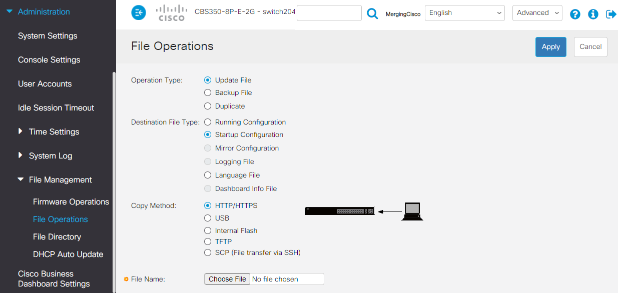
- Now click on Choose File and in the choose file window, browse to the configuration file you want to import.
Select the configuration file and click on Open. - Back in the main window, click on Apply to load your configuration file into the Startup Configuration.
Once imported, the switch will send a notification that the operation has been completed.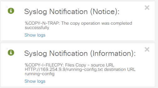
- You must now restart the switch for the changes to apply.
Click Administration > Reboot
Select Immediate and click on Reboot button.
Note that the device might take some time to reboot.