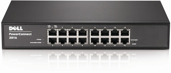
Dell Power Connect Manual Switch Configuration
Before Starting
Important! If you have problems accessing the switch for configuration when connected to the Merging MassCore PCIe Ethernet card (NET-MSC-GBEX1) please connect it to the PC’s on-board Ethernet port. When configuration is completed reconnect the switch to the MassCore Ethernet card.
Configure Network Addressing
- Right click on the Network icon in the Windows Taskbar.

Select: Open Network and Sharing Center
Click on: Change Adapter Settings on the left of the pane.
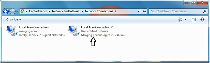
Right-click the Merging Technologies PCIe 8257 RAVENNA Network Card and select Properties:
(same procedure applies with any other network adapter)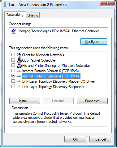
Select Internet Protocol Version 4 (TCP/IP) and Click on Properties:
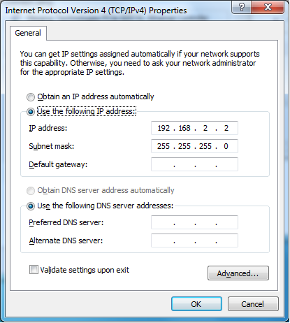
Click on the Use the following IP address: radio button and enter 192.168.2.2 (the DELL PowerConnect 28xx switch has a factory default IP address of 192.168.2.1).
Click on the OK button to accept the settings and close the dialog.
First access to the Switch
- To access the switch with a browser, the switch needs to be in Managed Mode. If the Managed Mode LED on the front panel of the switch is not lit, use a paper clip to press the Managed Mode button through the small hole on the front right of the switch. Once the Managed Mode led is lit, the switch offers a web gui. It is also possible to configure the switch using the 9-pin serial connection at the back of the switch. If this is how you want to configure it, please refer to the switch's documentation.
- Open a Web Browser (Internet Explorer is recommended for this configuration process.)
- Enter http://192.168.2.1 in the address bar and hit Return to access the Switch.
- Login using the default credentials:
user: admin password: admin
(Depending on the exact switch this field may need to be left blank. If in doubt consult the Dell 2816 Switch user guide.)
Note: If you cannot access the Switch remotely perform a reset to default factory settings. On the Dell Power Connect use a paper clip and press and hold for around ten seconds the button accessed via the small hole labeled Managed Mode to the right of the RJ-45 connectors. Afterwards make sure the indicator light Managed Mode to the left of the RJ-45 connectors is lit in order to access and configure the switch. (Press the button once again briefly if necessary.) Repeat the reset procedure in the future if remote access does not work first time. It may take two or three minutes for the switch to become available after a reset.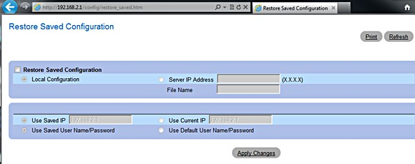
- Click on Apply Changes
Once logged into the switch select Change Configuration.
Note: The switch will then reboot (taking 2-3 minutes to do so)In the left-hand pane click on System > IP addressing to expand it and click on IP Interface parameters
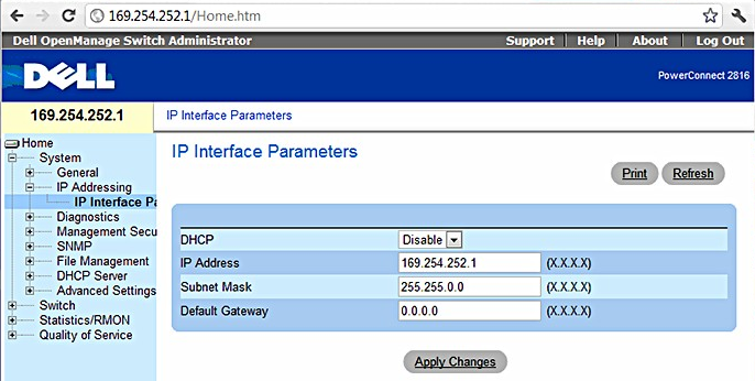
Set the IP Address to 169.254.252.1 see screen shot above.
Click on Apply Changes. The connection to the switch will then be lost since the Merging Network card still has a fixed IP in a different range.
Continue with points 9 to 12 to put the card back in IP auto-configure mode.Open the Windows Control Panel and open the Network and Sharing Center.
Select Change adapter settings
Locate and select the Merging Technologies PCIe Ethernet card connection and Right-click on it
- Select properties from the drop-down menu to open the Local Area Connection Properties dialog:
Select Internet Protocol Version 4 (TCP/IPv4) to select it and click on Properties to open the properties dialog:
This time choose the Obtain an IP address automatically radio button.

Click on OK to accept the settings and close the dialogue. Repeat to accept the settings and close the Local Area Connection Properties dialog.
Configure the switch
Now you can log into the switch using http://169. 254 . 252 . 1
Note: If you cannot access the switch once it is set to Obtain an IP address automati- cally try setting the adaptor to 169.254.252.2 and retry. Ensure that after configuring the switch the setting is changed back to Obtain an IP address automatically.
The following steps will help you to configure the Switch for dedicated RAVENNA networking. First ensure you can access and log on to the Switch.
- Open the System > DHCP server > DHCP Server Properties
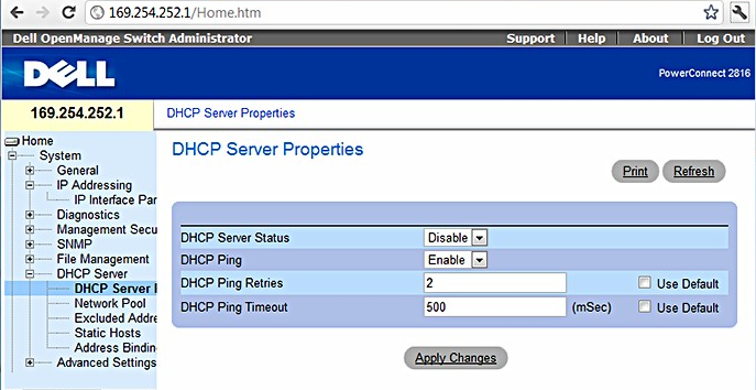
Set the parameters as in the screen shot above.
Click on Apply Changes.
Open the Switch > Ports > Port Configuration page and select Show All:
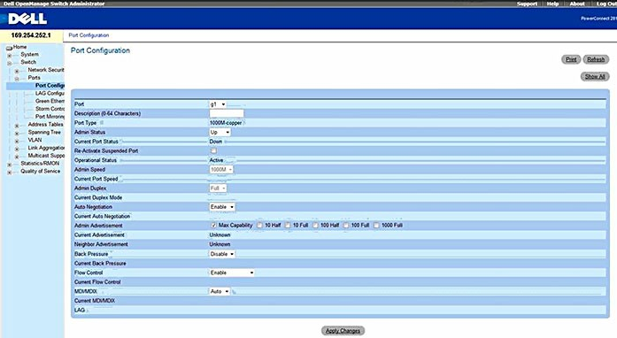
Set all the Flow Control entries to Disable:
This setting minimizes latency on the RAVENNA Network.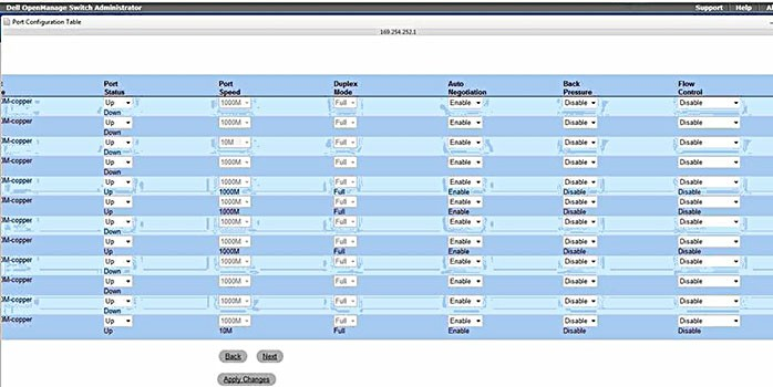
Open the Switch > Ports > Spanning Tree > STP Port Settings page:
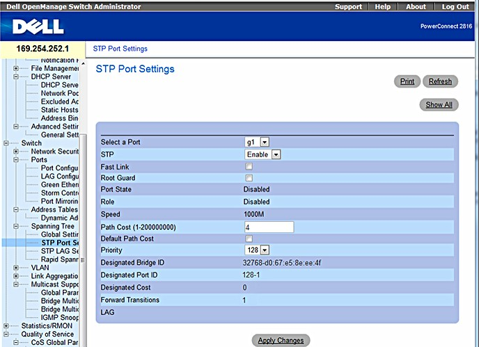
Click on Show All
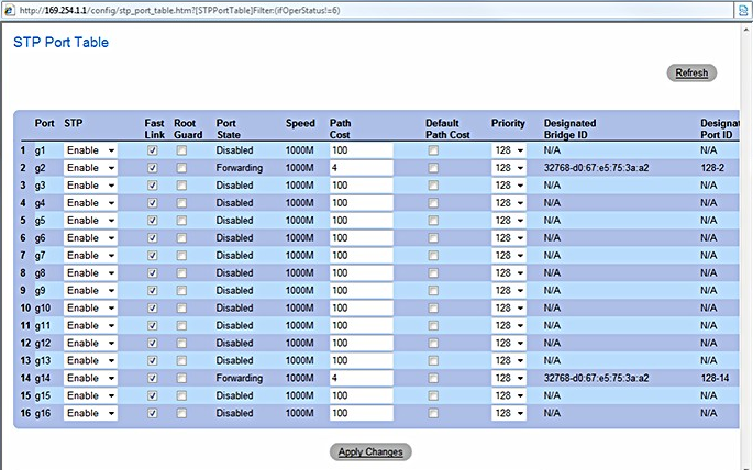
- In the STP Port Table window, check all Fast Link check boxes as shown in the screen shot above.
Note: Please ignore the 4 numeric entries in the Path Cost column and the Port State entries since these are derived from your current connection so these values may vary. - Click on Apply Changes.
- Open the Switch > Ports > Green Ethernet page:
- Set both Link Down Energy Detect Mode and Link Short-Reach Energy Detect Mode to off.
Open the Switch > Multicast Support > Global Parameters page.
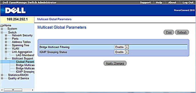
- Set both drop-downs to Enable as in the screen shot above.
- Open the Switch > Multicast Support > IGMP Snooping page:
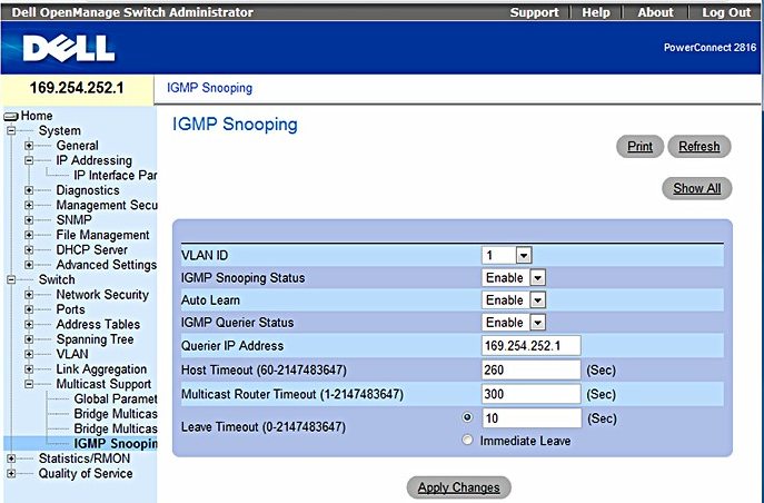
- Configure IGM Snooping as in the screen shot above. Querier IP Address needs to be the fixed IP address of the switch itself.
- Click on Apply Changes.
- Open the Quality of Service > CoS Global Parameters > CoS Settings page:
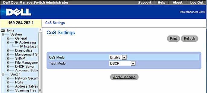
Configure CoS settings as in the screen shot above.
Click on Apply Changes.
- Open the Quality of Service > DSCP to Queue Mapping page:
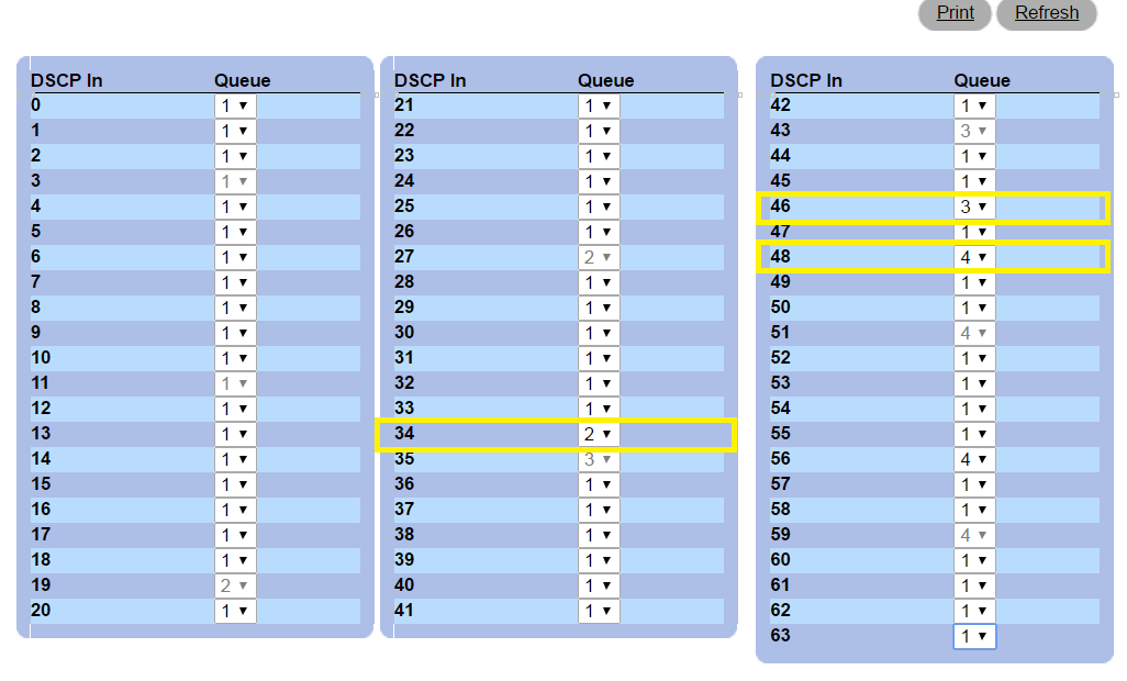
Configure DSCP to Queue Mapping as in the screen shot above. (note that some DSCP cannot be modified on the switch)
Click on Apply Changes.
- Log out of the switch which is now configured properly.