...
| Info | ||
|---|---|---|
| ||
1x VLAN for the Ravenna AES67 and 1x VLAN for regular networking. By default the switch already has VLAN1 created with defaults for regular networking. |
Table of contents:
3.1 Add a new VLAN
3.2 Add Ports to VLAN2
3.3 Change Device IP for VLAN2 (optional step, but recommended)
3.4 Change IGMP settings for VLAN2.
3.5 Change Green Ethernet settings.
3.6 Change QoS settings.
Adding a VLAN for Ravenna Networking.
...
First step is to change the IP configuration to use a APIPA (Automatic Private Internet Protocol Addressing) type of IP.
The administration page will then be only accessed trough this new IP.
Putting this in an APIPA IP range (169.254.0.0/16) will ensure that you can always access its administration page.
Ravenna devices generally use APIPA IP range to communicate over the network.
- In the Getting Started page, click on Change Device IP Adress
- Click on the Add button at the bottom of the IPv4 Interface Table.
- Set the IP Address type to Static IP Address.
Enter 169.254.1.254 in the IP Address field.
For the Mask setting, select Prefix Length and enter 16.
That will make your switch administration page respond to that IP address.
Note that we used Prefix Lenght instead of Network mask (16 is the same as 255.255.0.0).
But you could also set it to 255.255.0.0 it would also work. - Click on Apply to save the changes.
The switch will now change its IP address, therefore the 192.168.1.254 page you are actually using will stop responding. - The switch is now only accessible on HTTP://169.254.1.254
You will probably need to change to change your computer IP to "Obtain an IP address automatically" - Enter 169.254.1.254 in your browser, and enter your credentials.
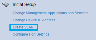
- In the Getting Started page, click on Create VLAN.
- Click on the Add button at the bottom of the VLAN Table.
- Set the VLAN ID: 2 and enter a VLAN NAME (can be anything you want).
Make sure VLAN Interface Status and Link Status SNMP Traps are both active.
Click on Apply once done.
Adding ports to the new VLAN2 we created in previous step.
...


