3. SG-350 - Dual VLAN configuration
- David Jacques
This guide will explain how to setup your SG350 switch to use 2 VLANs.
Adding VLANs.
1x VLAN for the Ravenna AES67 and 1x VLAN for regular networking.
VLAN1 : will be used for regular networking.
VLAN2 : will be used for Ravenna AES67.
By default the switch already has VLAN1 created with defaults for regular networking.
So we will be adding VLAN2 for the for the Ravenna AES67 networking.
Once connected to the switch :
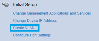
- In the Getting Started page, click on Create VLAN.
- Click on the Add button at the bottom of the VLAN Table.
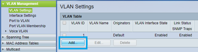
- Set the VLAN ID: 2 and enter a VLAN NAME (can be anything you want, please do not use special characters).
Make sure VLAN Interface Status and Link Status SNMP Traps are both active.
Click on Apply once done.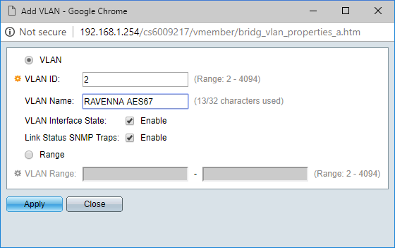
- Go to VLAN Management > PORT TO VLAN,
In the Filter section, set the VLAN ID to 2, and Interface Type to Port.
Click on Go.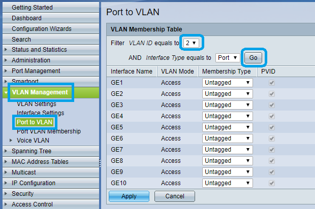
- Now you can see that all ports for VLAN 2 are excluded, you need to assign the required ports to this RAVENNA/AES67 VLAN.
Set the required ports from Excluded to Untagged (in the picture below, ports 5 to 8 and port 10 are assigned to VLAN 2.
Click on Apply once done.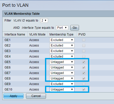
- You may now check your VLAN1 config.
In the Filter section, set the VLAN ID to 1, and Interface Type to Port.
Click on Go.
You can see that the ports you have added to VLAN 2 are excluded from VLAN 1.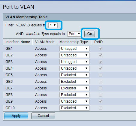
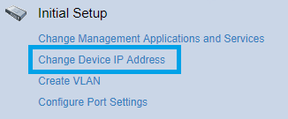
In the Getting Started page, click on Change Device IP Adress
Click on the Add button at the bottom of the IPv4 Interface Table.
Make sure VLAN is set to 2
Set the IP Address type to Static IP Address.
Enter 169.254.1.254 in the IP Address field.
For the Mask setting, select Prefix Length and enter 16.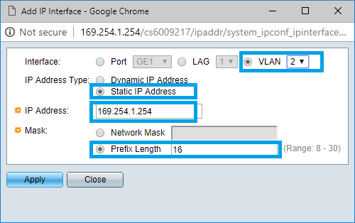
That will make your switch administration page respond to that IP address.
Note that we used Prefix Lenght instead of Network mask (16 is the same as 255.255.0.0).
But you could also set it to 255.255.0.0 it would also work.- Click on Apply to save the changes.
- The switch will now change its IP address, therefore the 192.168.1.254 page you are actually using will stop responding.
- The switch is now only accessible on HTTP://169.254.1.254
You will probably need to change to change your computer IP to "Obtain an IP address automatically"
Please make sure you are physically connected to a port assign to VLAN2 (in our example, port 6)
Note : you can do the same operation for VLAN1, to be able to access the Management interface for both VLANs.
But you have to use another IP address (192.168.1.254 for example) - Enter 169.254.1.254 in your browser, and enter your credentials.
- On the left pane menu, click on MULTICAST.
- Then click on IPV4 Multicast Configuration to expand it.
Click now on IGMP SNOOPING.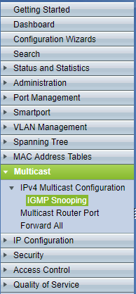
- In the IGMP Snooping page, enable both the IGMP Snooping Status and IGMP Querier Status checkboxes.
Then click on on Apply.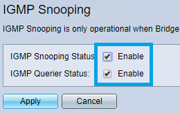
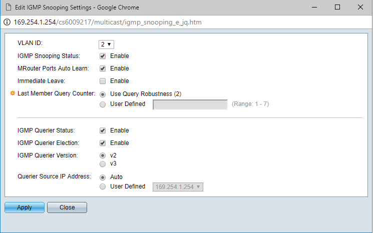
- On the IGMP Snooping Table, click on the radio button next to VLAN 2 to select and then click on Edit.
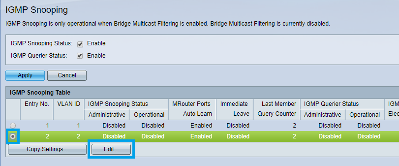
- Configure the IGMP Snooping Settings as on the picture below, and click Apply once done.
By default, Green Ethernet settings are applied, this needs to be disabled.
Please browse to Port Management > Green Ethernet > Properties
Untick both Energy Detect Mode and Short Reach, and untick 802.3 Energy Efficient Ethernet (IEEE) as well.
Click on Apply once done.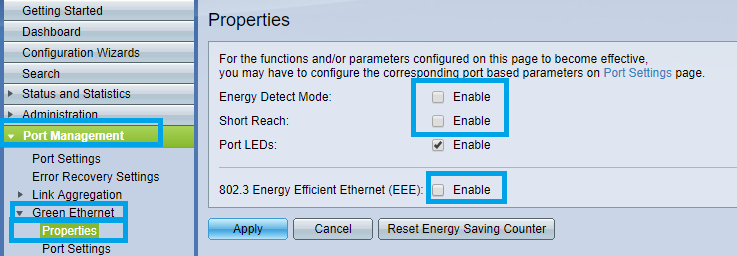
Browse now to Quality of Service > General > QoS Properties.
The QoS Mode should be set to Basic.
Click on Apply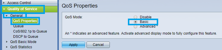
- Go now in Quality of Service > QoS Basic Mode > Global settings.
The Trust Mode should be set to DSCP
Click on Apply.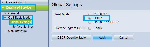
- Go back to Quality of Service > General, then DSCP to Queue.
Change the DSCP to Queue Settings as shown in the following picture and click Apply once done.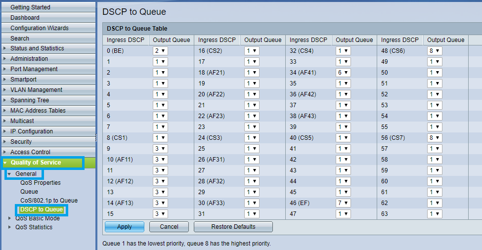
Note : Queue 34 : RTP AES67 / Queue 46 : PTP AES67 / RTP Ravenna / Queue 48 : PTP Ravenna / Queue 56 : PTP Dante Now is a good time to save the configuration.
Go in Administration > File Management > File Operations.
Select Duplicate as Operation Type.
Source File Name : Running Configuration
Destination File Name : Startup Configuration
Click on Apply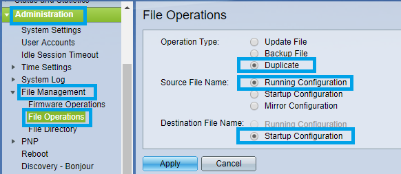
This will apply the current settings to the start up configuration.
In other terms that makes that configuration to be permanent (unless a reset of the device is done).You must now restart the switch for the changes to apply.
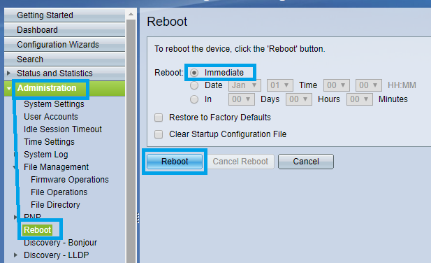
Click Administration > Reboot
Select Immediate and click on Reboot button.
Note that the device might take some time to reboot.